
Reference · Technical documentation
PDK Deep Dive.
Every chapter answers one question: what kind of engineering gives the human nervous system nothing to distrust?
This is the complete engineering reference for the PDK, the Portal Development Kit, and the disclosure behind the phrase research-grade motion platform: architecture, motors, patent, sensors, control system, power, protocol, safety, envelope and full specifications. Written for engineers, integrators and researchers who want the numbers and the reasoning behind them. The technology page is the short version.
Command to actuator
2,097,152 positions per rev
Burst, domestic outlet
PDK platform footprint
Contents
Chapter contents
- 01Stewart-Gough Platform ArchitectureWhy parallel kinematics, and what error averaging actually buys.Note · error stacking
- 02Direct-Drive BLDC Motor SystemSix outrunners, three controllers, zero backlash.Notes · backlash, rate ladder
- 03Patent CA 3217174 CA dynamically programmable air spring: the invisible pillars of air.Note · torque budget
- 0421-Bit Magnetic Encoders2,097,152 positions per revolution, and why 14-bit isn't enough.Note · resolution
- 05The Control SystemBare-metal, 1kHz internal, and the derivative most platforms ignore.Notes · the millisecond, snap
- 06Power Architecture1.41 farads, 30kW burst, one domestic socket.Note · the burst
- 07Integration & API42 bytes of UDP and an open WebSocket registry.Note · the packet
- 08Safety ArchitectureThree layers, and exactly what each one catches.Note · break it
- 09The Motion EnvelopeSix axes, and the trick that makes them feel bigger.Notes · six axes, envelope, the cue
- 10Complete SpecificationsEvery number in the document, in one place.Note · spec index
Chapter 01
Stewart-Gough Platform Architecture
Before the motors. Before the patent. Before the software. The reason the PDK performs the way it does starts with one decision at the foundation of the design, and it is a decision about error. The answer is Stewart platform kinematics: a parallel, six-leg mechanism that distributes load across every actuator simultaneously. It's the same architecture chosen by flight simulators and some surgical robotics for the same reason. Not because it is the most sophisticated option, but because it removes the most sources of mechanical uncertainty between command and human perception.
Note 01 · Error stackingHow six leg errors combine
Step 1 gives all six legs a random error. Step 2 combines those same six numbers two different ways: a serial chain adds them, a parallel platform averages them. Step 3 repeats the whole thing 600 times so you can see the two outcomes as distributions rather than single results. The copper spike sits inside the steel mound: same parts, same flaws, same 600 builds, but the parallel architecture lands near zero almost every time. Illustrative model, not a measured PDK tolerance. Parallel mechanisms average actuator error rather than stacking it; the exact ratio here is a property of the arithmetic. Real platforms map leg error to pose error through the Jacobian, so it varies across the envelope.
How does a Stewart platform work, and why does ARK use one?
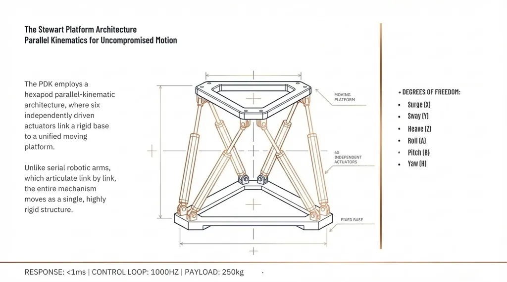
A Stewart platform is a parallel kinematic mechanism. Six actuators connect a fixed base to a moving platform simultaneously, and the motion of each one is resolved with the other five. Each one a leg, each leg working in concert with the other five.
This is fundamentally different from the way most machines move. In a conventional serial mechanism, a robotic arm, a crane, most industrial equipment, forces travel through joints in sequence. Joint one moves, then joint two responds, then joint three. The platform at the end is the last in a chain.
In a parallel mechanism there is no chain. Every actuator connects directly to both the base and the platform at the same time. Every leg contributes to every movement simultaneously. That single architectural difference is the origin of most of what makes the PDK unusual.
The four structural advantages
1 · Rigidity
Load applied to a serial mechanism is carried by whichever joint is closest to it. That joint bears the full force before passing it on. In a parallel mechanism, load distributes across all six actuators at once. The platform withstands significantly higher forces and moments than a serial chain of equivalent weight and cost, because no single component is the weak point. Commanded to hold position under a person shifting their weight, it doesn't flex. It holds.
2 · Error averaging
The instrument above is this advantage, made visible. Individual actuator imperfections average out instead of stacking into a compounded error. Not because each actuator is perfect, but because the architecture makes individual imperfections irrelevant. In practice this is what eliminates the micro-jitters that surface in stacked-error serial rigs during slow, sustained cornering. It's the kind of mechanical noise a driver feels before they can name it.
3 · Dynamic response
Every axis of movement engages the full mechanical system simultaneously. When the platform moves forward, all six legs contribute. When it rolls, all six legs contribute. There is no sequential activation, no lag while a downstream joint catches up. In a serial mechanism that compounding lag is felt as a chassis dragging behind the visual input, the rig catching up to the screen instead of moving with it. This is the mechanical basis for sub-millisecond command-to-actuator latency, from motion command to actuator onset. The architecture doesn't fight the motion. It delivers it.
4 · Compact workspace
A Stewart platform achieves full 6-DOF motion within a footprint significantly smaller than serial mechanisms of equivalent range. The PDK moves through six degrees of freedom resolved through real-time inverse kinematics, within a constrained but precisely characterised envelope: 158.23 mm surge, 143.85 mm sway, 117.3mm heave, 19.60° yaw, 16.0° pitch, 17.3° roll total travel, all within 1.00 × 1.00 m. Chapter 9 maps the envelope axis by axis.
Production configuration
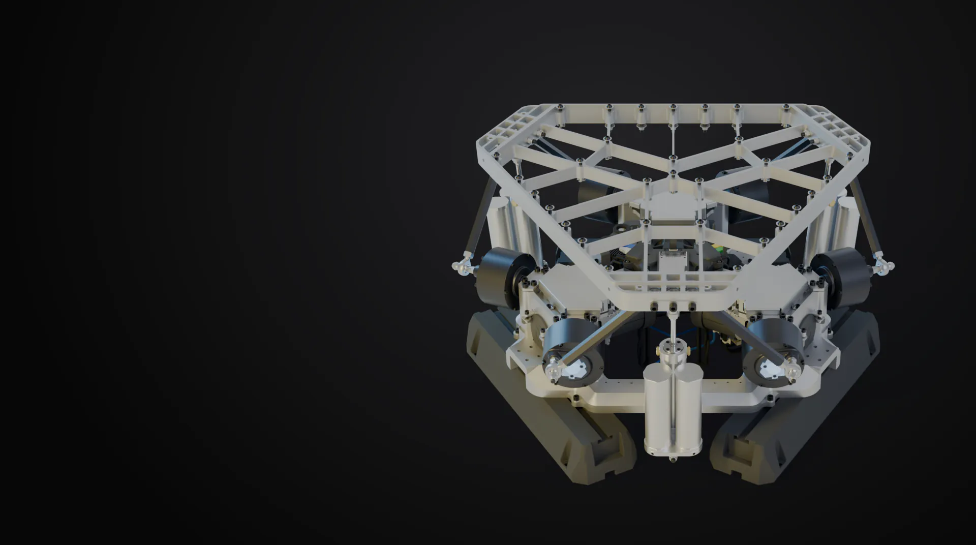
The production platform uses a triangular-base / triangular-platform geometry: six motors arranged in three pairs at 120-degree intervals, mounted on a triangular aluminium extrusion frame with precision-machined motor-pair brackets at each vertex. The platform joints are tightly grouped into three pairs, giving the moving platform its distinctive triangular shape.
Each of the six kinematic chains consists of a direct-drive rotary actuator, a 47mm eccentric arm, and a 300mm connecting rod with 30-degree ball joints at both ends. The rotary output drives each leg through the crank mechanism, converting rotation to linear motion with an effective stroke equivalent to a 94mm linear actuator. Universal joints at both ends allow rotation in any direction, so the platform is never mechanically constrained to move in only one plane.
Key insight, isotropy: Platform isotropy means the force required to move the platform is the same regardless of direction. Anisotropic designs feel different depending on which axis you're testing. They lie about their performance in real mixed-DOF scenarios. The production platform's 3×2 geometry maximises isotropy: it resists loads equally well in all six degrees of freedom.
Inverse kinematics
The coordinated action of all six legs, each at a precisely calculated position, defines the platform's pose at any given moment. The inverse kinematics that calculates those lengths runs at 3.3 kHz, fed by a 1 kHz pose-command stream; both are internal rates. It receives the desired platform position and orientation, computes the exact length required from each of the six actuators, and sends those commands to the motor controllers.
That calculation, inverse kinematics, is a closed-form mathematical solution. Telemetry enters one algebraic equation. The exact required actuator lengths emerge in a single pass. An iterative solver would have to guess an angle, check the resulting platform position, refine, and guess again; that process can take hundreds of microseconds and depends on convergence to reach an answer. The closed-form pipeline runs in under 10µs on the ARM Cortex-M7, leaving the remaining 990µs of every millisecond cycle for motor control, safety verification and telemetry.
Stewart platforms have known kinematic singularities at workspace edges, configurations where the inverse-kinematics maths becomes degenerate. The PDK's firmware iteratively maps these singular boundaries and sets the software workspace inside them, so the closed-form solution always operates in well-conditioned configurations. Chapter 8 covers the full workspace enforcement system.
Parallel kinematics removes the most sources of mechanical uncertainty between a motion command and what a human being feels.
That is the starting point. Every chapter that follows is a consequence of the same question.
Chapter 01 in one line
Six legs share every load, so no single error ever reaches the seat.
Chapter 02
Direct-Drive BLDC Motor System
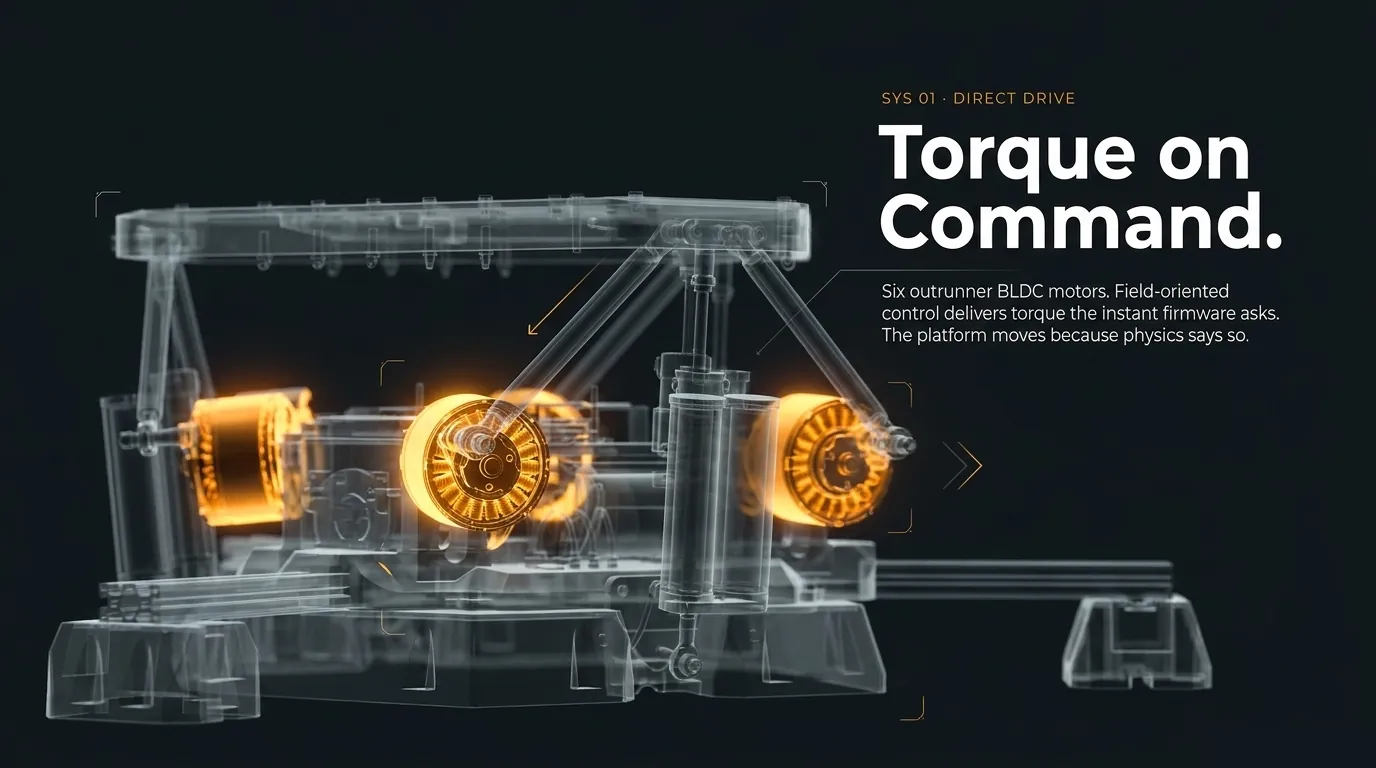
Six brushless DC outrunner motors with field-oriented control. No gearboxes, no belts, no reduction stages. Therefore no gear slop, no mechanical backlash, no compliance to filter around. Each motor connects directly to its actuator rod in closed-loop direct drive. Zero mechanical intermediates between game signal and physical motion.
Note 02 · BacklashWhat a reversal costs
Push the command one way, then reverse it. The direct-drive trace follows instantly. The geared trace stalls in the dead band while the motor takes up the slop between gear teeth, then catches up. In motion simulation that stall is felt as a lag between input and response, and it recurs at every single direction change. In a corner, that is constantly.
Why outrunner BLDC
Outrunner motors place the rotating magnets on the outside of the stator, producing higher torque at lower RPM than equivalent inrunners. For a direct-drive actuator that must hold position and deliver burst force without a gearbox, this torque density is critical.
The motors are custom-specified conversions of high-performance hoverboard motors, selected for their magnetic design and structural integrity under the combined radial and axial loads of the Stewart platform geometry.
Each motor is mounted on a large CNC-cut aluminium bracket plate at one of the chassis's triangular vertices, paired with its kinematic partner. These bracket plates are the platform's most prominent structural element, and they align each motor's axis with the platform's kinematic geometry rather than a purely radial direction.
What direct drive eliminates that geared systems can't
With direct drive, the motor output connects to the actuator without any intermediate mechanism. The motor turns, the actuator moves. One-to-one. Nothing in between. This removes four failure modes that every geared platform carries:
Backlash
Every gear mesh has play, a small gap between gear teeth that creates slop. When a geared system reverses direction, the motor must first take up that backlash before the actuator responds. Direct drive has no gears, so it has no backlash. The command and the motion are the same event.
Friction and stiction
Gearboxes introduce sliding friction and stiction, the resistance that must be overcome before motion begins. Stiction is particularly problematic for high-fidelity simulation because it creates a dead zone around neutral where small inputs produce no response. Direct drive removes gearbox stiction and transmission dead zones entirely. The motor responds to the smallest commands the control system can generate.
Mechanical delay
A transmission is a physical structure with compliance. It bends, stretches and absorbs energy before transmitting it, and that compliance introduces delay between command and response. Remove the transmission, remove the delay.
Maintenance
Gearboxes require lubrication, wear over time, and eventually need replacement. Direct-drive motors have no consumable mechanical components in the transmission path.
Six motors, three controllers
The PDK's six actuators are managed by three dedicated ARK Drive motor controllers running field-oriented control (FOC). Each ARK Drive handles two motors, with each pair operating as a coordinated unit within the broader six-axis system.
Three independent controllers means three independent closed-loop control systems operating in parallel. No single controller is responsible for coordinating all six axes. That coordination happens at the platform control layer above, which sends position targets to each ARK Drive via CAN bus at 1kHz, an internal rate. Each controller then executes its own inner control loop at a much higher frequency to achieve those targets.
What field-oriented control does
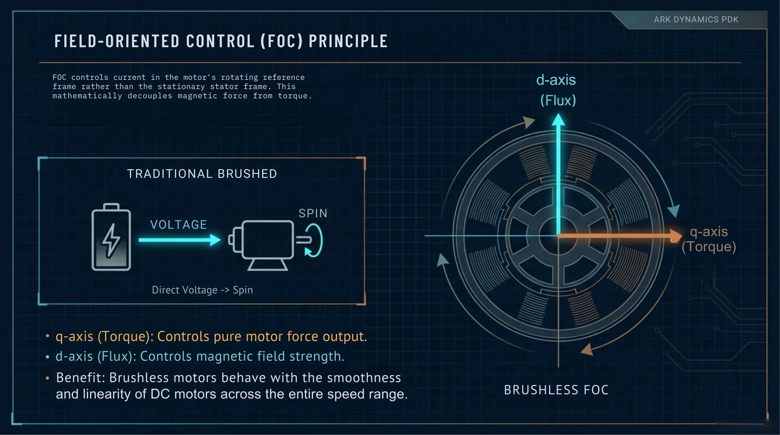
A brushed motor is driven by applying voltage; its physical commutator switches current through the windings automatically. A brushless motor has no physical commutator, so the control system must electronically manage three-phase current at all times to produce smooth torque.
Field-oriented control transforms the motor's electrical state into a rotating reference frame that moves with the magnetic field. In that frame the motor's behaviour simplifies: one current component (the q-axis) directly controls torque, another (the d-axis) controls magnetic flux. Controlling them independently lets ARK Drive deliver precise, smooth torque at any motor speed, including zero speed, where motion platforms spend much of their operating time.
One known limitation of direct-drive motors is thermal load at zero speed. A motor holding a static weight without a gearbox to back-drive the load pulls continuous current to fight gravity, generating heat in the stator. On the PDK the platform's static weight is carried by a dynamically programmable air spring (Chapter 3), so the FOC algorithm is free to dedicate its full current output to dynamic motion. The motors stay cool because they are never asked to hold the rig up. They are only asked to move it.
Two rates, two jobs
Note 03 · The rate ladderFour clocks. They are not the same number.
These four rates get collapsed into one figure constantly, and they are not interchangeable. MCP input is how fast telemetry can arrive. HKP is where the platform sits. ARK Drive is what the motor is doing between those position updates. DSP is dedicated signal processing above the control loop.
| ARK Drive update loop | 8kHz (every 125µs). Current, velocity and position control update together in a single shared cycle, directly controlling the electromagnetic force the motor produces. |
|---|---|
| HKP position loop | 1kHz, internal, fed by the 3.3 kHz platform kinematics calculation. Sends targets to each ARK Drive, which resolves them through its own 8kHz update. |
The 8kHz ARK Drive update reproduces high-frequency texture: gravel under the tyres, kerb noise, engine vibration buzzing through the chassis, plus the fine speed and force corrections that keep the actuators moving smoothly rather than mechanically. The 1kHz HKP position loop manages where the platform sits: a sustained lean in a banked turn, a held trim under steady load.
Why this matters: The ARK Drive's update runs 8× faster than the platform-level position rate. The motor is constantly correcting toward its target, not just jumping to it once per millisecond. Position holding, small corrections and low-speed movements are executed with the same precision as high-speed dynamic motion.
| Topology | BLDC outrunner, 3-phase |
|---|---|
| Count | 6 (one per actuator leg) |
| Controller | ARK Drive (3 units, 2 motors each) |
| Control mode | Field-oriented control (FOC) |
| Bus voltage | 53.3V nominal |
| Continuous current | 56A per rail |
| Peak power | 30kW (cap-bank-assisted burst) |
| Transmission | None — direct drive |
| CAN bus speed | 2 Mbps |
The direct-drive advantage: Motor torque reaches the platform through no transmission. No gear-friction losses in the path. No torque ripple from backlash. No added mass from reduction stages. The motor IS the actuator.
The signal and the motion are the same event. There is nothing in between for the nervous system to distrust.
Chapter 02 in one line
No transmission. The command and the motion are the same event.
Chapter 03
Patent CA 3217174 C: The Invisible Pillars of Air
The motors should never be fighting gravity. They should be delivering motion. A dynamically programmable mechanical separation of those two demands — not fixed like a spring, not slow like active electronics — is what Patent CA 3217174 C protects, and what gives every other chapter in this document the dynamic performance it describes. Inventors: Louis Hajichristou & Michael Gregoriades.
Note 04 · Where the torque goesWhere the torque goes with a rider aboard
Schematic, not to scale. The point is the split, not the ratio. Follow the rider's weight down. On a conventional platform it lands on the motors, so every kilogram added to the seat is torque permanently subtracted from the motion budget, at all times, in every axis. On the PDK it lands on the air spring, and the motor's whole arrow is motion. Add a heavier rider and watch the conventional bar shrink while the PDK bar holds. Switch the air spring off to see the PDK become a conventional platform. Holding current is also heat: current through a winding that is moving nothing is pure resistive loss, which is why conventional platforms need oversized motors and cooling. At the calibrated neutral pose, motors need approximately zero holding force, within roughly ±1% of target.
The problem every motion platform has always had
A motion platform must do two things simultaneously. It must hold the full weight of the platform structure, the seat and the person sitting in it against gravity, at rest, at any position in its range. This is a static problem: constant, predictable, unrelenting.
It must also move. Precisely, instantly, and with enough force to produce motion the nervous system perceives as real. This is a dynamic problem: changing continuously, in all six axes, faster than human perception.
The paradox is that both demands are placed on the same motors. Every motor in a conventional platform is simultaneously holding the platform up and trying to move it. The holding demand consumes a significant fraction of each motor's output capacity at all times, capacity that is then unavailable for motion.
The industry's answer for decades was to oversize the motors. Buy enough motor to cover both demands. Accept the cost, the heat, the power consumption and the reduced dynamic bandwidth. This is why professional motion platforms cost what they cost.
What had been tried before
Counterweights
Add mass opposite the platform to balance gravity. This eliminates the static holding demand, but counterweights add inertia. The motors must now accelerate the platform, the occupant and the counterweight mass. The platform that was easier to hold becomes harder to move quickly.
Mechanical springs
Mount springs alongside the actuators to carry some of the gravitational load. But spring force varies linearly with extension: Hooke's Law. A spring tuned to balance at mid-stroke is over-supporting at full extension and under-supporting at full retraction. Change the payload and the calibration is wrong. Springs are rigid in a system that needs flexibility.
Active pneumatic or hydraulic compensation
Use valves to adjust pressure dynamically, tracking platform position and payload in real time. Better than springs, but it introduces a control loop with latency. Valve response times are measured in tens of milliseconds. Adding a 50–200ms compensation system to a platform designed for sub-millisecond command-to-actuator latency is architecturally incoherent.
All three share a common failure mode: they solve part of the problem while creating a different problem of equivalent severity.
The insight
The breakthrough in CA 3217174 C is not the use of pneumatics. Pneumatic lift systems are not new. The breakthrough is an architectural insight about the nature of the two demands.
Static loads and dynamic loads are fundamentally different in character. Static loads do not change rapidly; they change only when the payload changes, and between those changes they are effectively constant. Dynamic loads change continuously, limited only by the control system's bandwidth.
If two load types have such different time constants, they can be handled by two different systems, each optimised for its own domain. This is a dynamically programmable air spring: passive at the timescale of motion, not an active control loop, not real-time electronic compensation, and re-programmed (pressure re-trimmed) only between motion events, when the payload changes. A mechanical separation of two load types that have always been conflated.
The motors don't hold you up. They just move you.
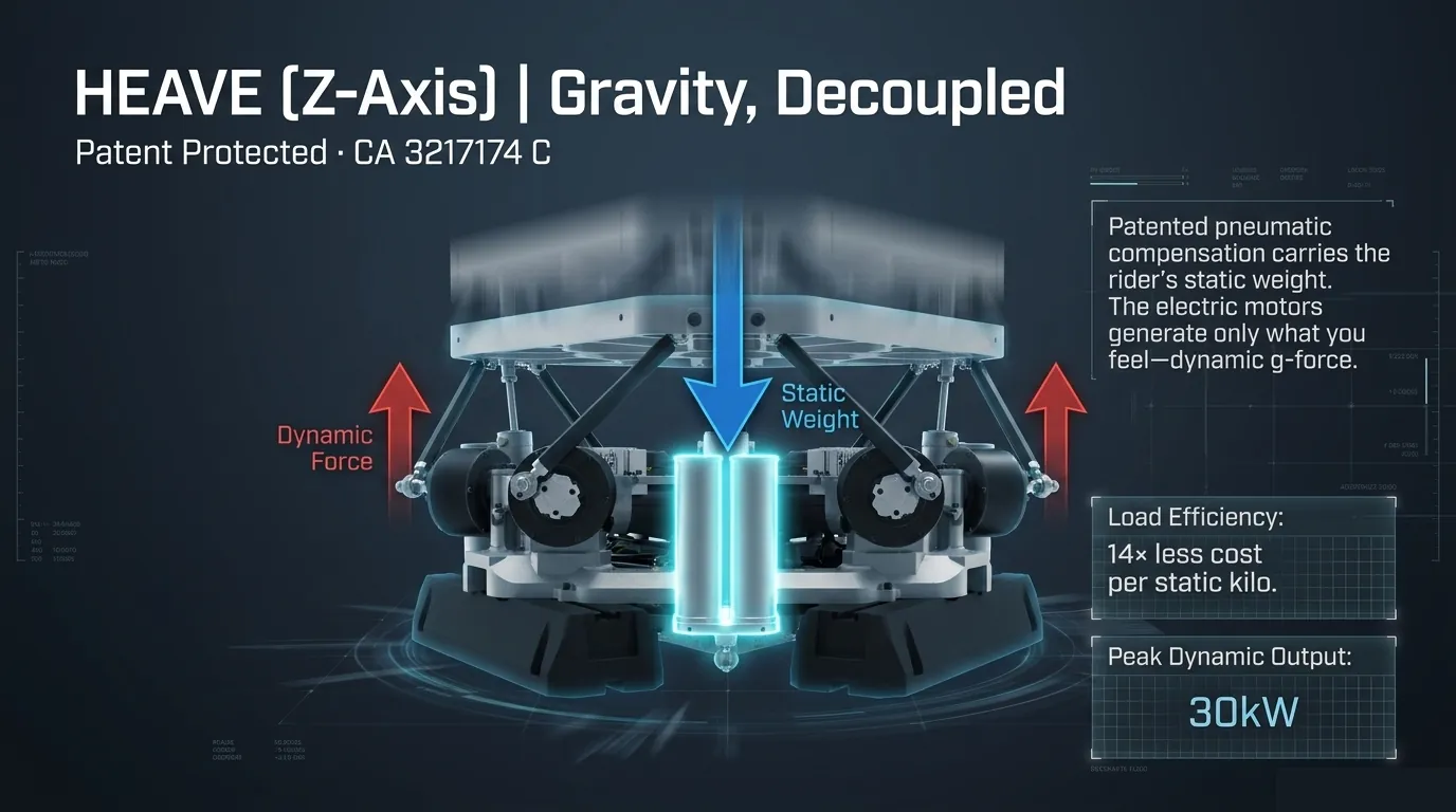
Core concept
Canadian Patent CA 3217174 C protects the system ARK calls Passive Weight Compensation: pneumatic cylinders carry the static load while the direct-drive motors handle only the dynamic forces, the mechanical separation behind its 1 kHz internal pose-command cadence. Compressed air springs work in parallel with the actuators to pre-load platform weight, making it effectively weightless from the motors' perspective. Three pneumatic cylinders, one per actuator pair, carry the static weight of platform and rider, each integrated into the kinetic configuration of the triangular base. Air pressure opposes gravity so the motors don't have to.
System components
- Pneumatic cylinders: one per actuator kinematic pair.
- Compressed air reservoir: each pneumatic cylinder carries two auxiliary dead-volume tanks that maintain system pressure and flatten the pressure curve. Without them, pressure fluctuates 5.03 bar across the cylinder's travel; with them, fluctuation drops to 0.36 bar, a 14× improvement. Without it a pneumatic spring gets stiffer as it compresses; with it, the spring constant approaches zero over the operating range.
- Pressure regulation: adjustable to match payload weight.
- Locked-pressure passive operation: once equilibrated, valves close at 0W. The pneumatics behave as mechanical air springs during motion.
- Slow-rate equilibration: re-trims pressure when motor current indicates a payload change. Runs at mount, dismount or major load events. Never in the 1 kHz internal motion loop.
- Onboard compressor: charges the reservoir at power-on and re-trims during equilibration under firmware control. No external shop-air connection required; the platform is self-contained and designed for standard domestic power.
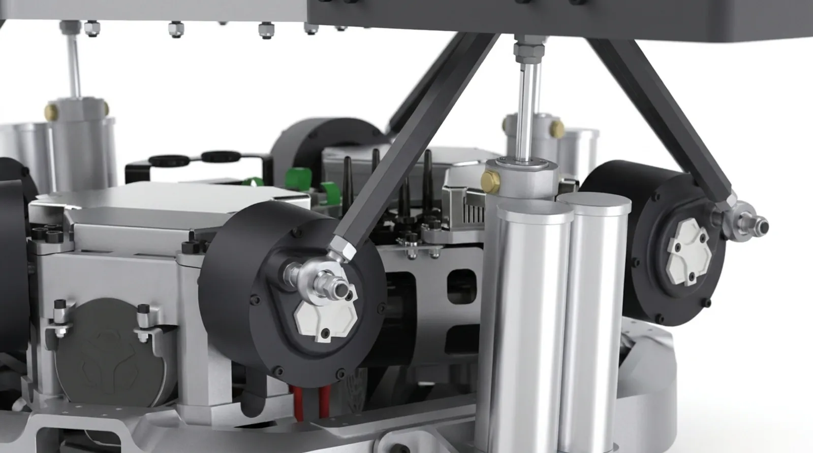
How it behaves
At static equilibrium: cylinders are pressurised to match each actuator's gravitational load. Motors need approximately zero force to hold position. The platform floats on air springs.
During dynamic motion: actuator extension increases cylinder volume, slightly dropping pressure (per PV = nRT). Retraction reduces volume, raising pressure for progressive spring response. Motors handle only these minor pressure variations plus the dynamic forces the rider should feel.
The key advantage: Static gravity loads stay permanently decoupled from motion demands. Motors focus on acceleration, not weight, which boosts efficiency, reduces heat and maximises dynamic performance.
Performance benefits
Force reduction
At the platform's calibrated neutral pose the air spring carries the full static load: motors need approximately zero holding force there, within roughly ±1% of target. Off that pose, as actuator geometry shifts through the range of motion, the pneumatic pre-load still carries the bulk of the static weight, leaving motors to handle inertia and friction rather than the platform's weight.
Thermal performance
With static holding current removed at neutral pose, heat generation (proportional to I²R) drops correspondingly. Operating temperature runs measurably lower than an uncompensated system across a session. The result: extended component life, reduced thermal throttling, and sustained peak performance over long sessions.
Dynamic response and efficiency
Motor torque is fully available for acceleration, not split between holding the platform up and moving it. Power consumption at idle is near zero, just friction compensation. The pneumatic system consumes 0W at steady state; brief active pulses occur only at payload-change events.
Failure mode: designed so there is no sudden drop. Air springs resist compression even at low pressure. On pressure loss the platform is designed to descend slowly to its mechanical stops.
What this means for the price
A conventional direct-drive platform achieving equivalent dynamic performance would require motors large enough to deliver the PDK's full dynamic force capacity on top of the static holding requirement. Those motors are larger, heavier, more expensive and run hotter, requiring more cooling, larger power supplies and higher-rated controllers.
Passive weight compensation lets the PDK use motors sized for dynamic performance only. The static problem has been mechanically solved; the motors do not need to solve it. The architecture is solving the right problem with the right tool, rather than using one powerful tool to solve two fundamentally different problems simultaneously.
When a motor is freed from fighting gravity, the human being in the seat receives that freed capacity as motion. The onset cue arrives faster. The force is more direct. The nervous system receives a cleaner signal. That is the content of Patent CA 3217174 C.
Static holding force at neutral pose
Electrical power at idle
Canadian patent, granted
Chapter 03 in one line
Air carries the weight. Motors carry only the motion.
Chapter 04
21-Bit Magnetic Encoders
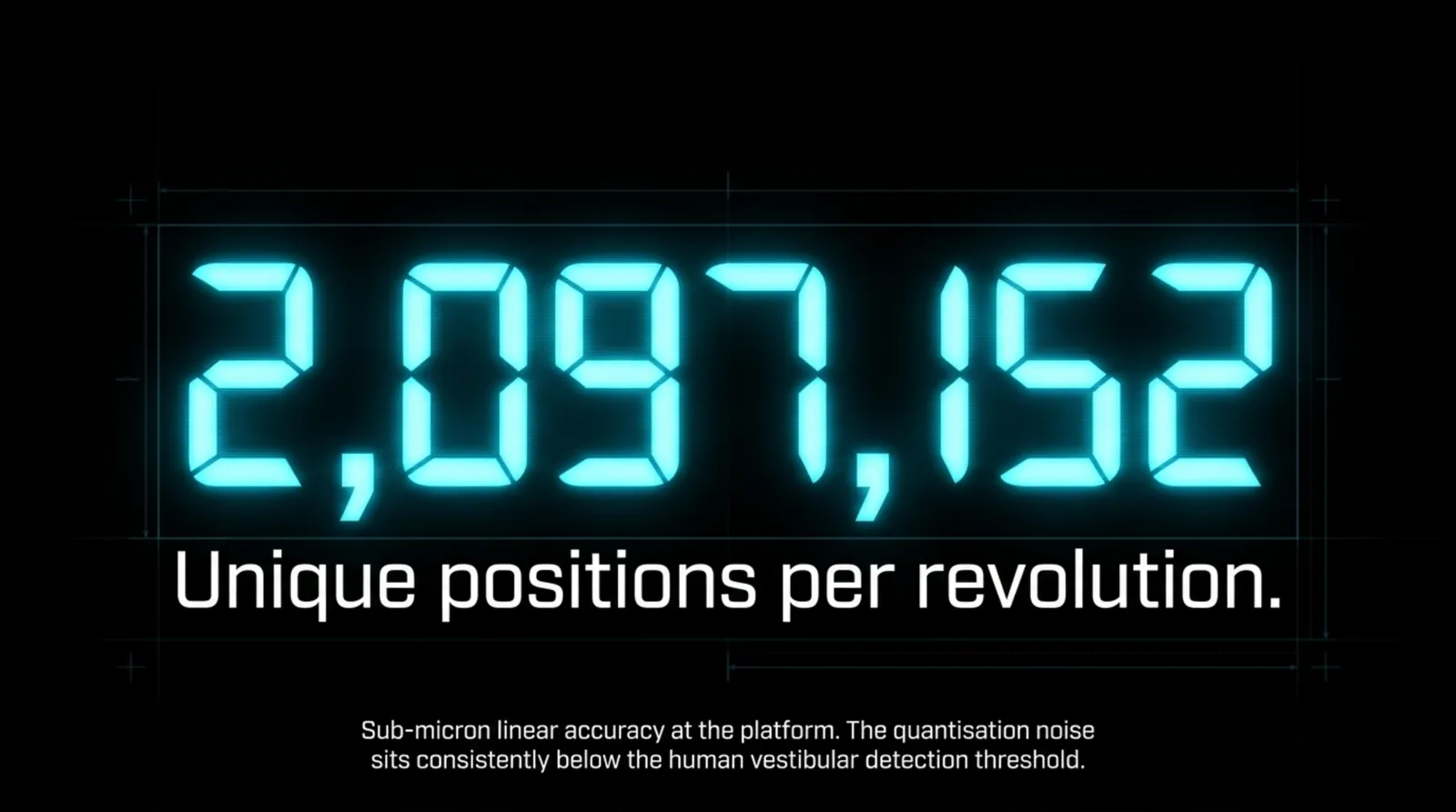
Each motor shaft carries an MT6835 magnetic position sensor. 21 bits of resolution: 2,097,152 discrete positions per revolution. Sub-micron sensing resolution at each actuator's encoder, with 1 kHz internal closed-loop position control.
Note 05 · ResolutionThe same motion, twice
The dashed line is the commanded motion. The solid line is what the control system can actually see. At 14-bit, magnify and the staircase appears. Those steps are a real signal in the control loop, and can surface as an unnatural stepped feel. At 21-bit the staircase is still there, but the steps are 128× smaller: small enough that encoder quantisation stops being the limiting factor in the chain. On this chart the step size is drawn far larger than life so a 14-bit step is visible at all; at true scale neither staircase would show without magnification. The 128× difference between the two settings is exact, and so are the counts: 16,384 against 2,097,152.
Why resolution matters
A 14-bit encoder, typical in prosumer motion platforms, gives 16,384 positions per revolution. That means 128× larger quantisation steps inside the control loop. Whether those steps become perceptible depends on the actuator geometry, the motion profile, and the load; ARK uses 21-bit feedback so encoder quantisation is never the limiting factor.
The MT6835 at 21-bit gives 128× more positions. The position steps become sub-micron, far below the threshold of any human sensor. Motion feels continuous because, at the encoder level, it effectively is.
High-frequency surface detail, kerb rumble, road texture, granular slip, is encoded in very small, very fast actuator movements. If position feedback can't resolve movements with enough resolution, those sensations are invisible to the control system and never reach the platform. Road texture, tyre grain, engine harmonics: these aren't simulated with large movements. They're reproduced with microscopic ones.
Absolute, not incremental
An incremental encoder counts position changes from the moment it is powered on. Lose power or miss a count and position is lost; the system must rehome before it can operate safely.
An absolute encoder reports its actual position regardless of power history. The PDK knows where every actuator is the instant it powers on, every time, without a homing routine.
Safety implication: A platform that requires a homing sequence every startup is also one power interruption away from a safety event. The PDK's absolute encoders are designed to remove that failure mode: position is known from power-up, with no homing move.
Magnetic, not optical
Magnetic encoders use Hall-effect sensing of a diametrically-magnetized disc. Unlike optical encoders they are more resistant to dust, contamination and vibration-induced misalignment. In the operating environment of a motion simulator, vibration, occasional condensation, long continuous run times, magnetic sensing is more reliable.
| Part | MT6835 magnetic rotary encoder |
|---|---|
| Resolution | 21-bit (2,097,152 positions/rev) |
| Interface | SPI to the ARK Drive; position relayed to the HKP via CAN bus at 2 Mbps |
| Sensing principle | Hall-effect, diametrically magnetized |
| Calibration | Factory-calibrated |
| Count per leg | 1 (on motor front plate) |
| Total encoders | 6 |
At 21-bit, encoder quantisation is substantially smaller than the platform's other mechanical and control-error sources. The goal is simple: the signal the platform delivers should be continuous, never stepped, with the encoder never the reason it isn't. That is why 21-bit matters where 14-bit does not. It is also the property that matters most in vestibular and human-factors research, where a stimulus often has to sit below the detection floor on purpose.
Chapter 04 in one line
2,097,152 positions per revolution: steps too small for any human sensor.
Chapter 05
The Control System: Real-Time Architecture
Two dedicated ARM Cortex-M7 processors running bare-metal. No OS, no abstraction layers. Every clock cycle is available for motion. The reason for bare-metal, for 1 kHz internal control, for deterministic timing is not engineering preference. It is biological necessity. Visual–vestibular timing strongly shapes how convincing motion feels, and added latency and jitter degrade it. The control architecture exists so the platform contributes as little delay and as little jitter as possible to the complete simulation chain.
Note 06 · The millisecondOne cycle, stepped through
The ring is one millisecond. Inverse kinematics, the calculation everyone assumes is the expensive part, is the thin copper sliver at under 10µs, about 1% of the cycle. The other 990µs is motor control, safety verification and telemetry. Every millisecond. Forever. The loop's value isn't that it's fast; it's that it is always exactly this fast.
Two processors, one purpose
The PDK's control intelligence runs on two ARM Cortex-M7 microcontrollers at 600MHz, both bare-metal. No operating system, no background processes competing for compute time. The two have distinct roles and communicate over 100 Mbit Ethernet.
HKP: Housekeeper Processor. Manages core operation: inverse kinematics, motor controller coordination via CAN bus, safety monitoring and telemetry. It is the authoritative source for platform state and the single point of command to the three ARK Drive controllers.
MCP: Motion Cueing Processor. Handles the external interface: receiving motion signals via UDP from FlyPT Mover (or any compatible UDP source), running a variable signal processing pipeline, and passing processed motion commands to the HKP. FlyPT Mover is third-party software, not ARK software; it is named here as the recommended interface, with attribution.
This division keeps the core control loop on the HKP isolated from the variable-latency work of parsing external signals and running motion cueing algorithms. The HKP's timing is deterministic. The MCP's timing can vary. They are separate.

What happens in each millisecond
Input processing. The latest motion command is read from the MCP interface. Acceleration and jerk limits shape the command into a physically executable trajectory. Safety constraints are checked against workspace boundaries and rate limits.
Inverse kinematics. The 6-DOF platform command, position and orientation, is converted to six individual motor positions. The calculation runs in under 10 microseconds and is verified against physical limits before the results are used.
Command transmission. Position targets are formatted as CAN messages and transmitted to the three ARK Drive controllers over the 2 Mbps bus. Each message includes velocity limits, torque limits and a watchdog heartbeat.
Feedback acquisition. Encoder positions, motor currents, velocities and temperatures are read from all six motors. Data integrity is validated via CRC checks and range verification before the data is used.
Safety monitoring. Position, velocity, current and temperature limits are checked. Encoder agreement is verified. Communication health is confirmed. The watchdog timer is updated.
Sub-millisecond command-to-actuator latency
Control-loop latency, the time from a motion command being issued to an actuator beginning to move, is under 1 ms. Below one millisecond, command to actuator onset.
The contributing stages are: command processing through the MCP interface, inverse kinematics computation (under 10µs), CAN bus transmission to the ARK Drives on the 2 Mbps bus, and the motor controller's FOC response initiating current output to the motor phases. Each stage contributes a measurable portion. The sum is under 1 ms, command to actuator.
Scope of this figure: This latency describes the PDK control loop, from motion command to actuator response. Total perceived latency in a sim rig also depends on the PC, the game engine and the motion software in the chain.
Motion profile generation
Raw position commands, step inputs from a simulation, create discontinuous motion. Instantaneous velocity changes imply infinite acceleration, which implies infinite force. The control system generates smooth motion profiles that execute the commanded motion within the physical constraints of the platform.
Acceleration limiting. Maximum acceleration is configurable per application: 1–2G for sim racing, 0.5–1G for flight simulation, 0.2–0.5G for general VR. This prevents mechanical shock and ensures the motion feels natural rather than mechanical.
Jerk limiting. Jerk is the rate of change of acceleration. Unlimited jerk produces motion that begins and ends abruptly. Physically achievable, perceptually wrong. The PDK applies jerk-limited motion profiles, producing smooth onset and termination of accelerations. The difference between a jerk-limited and a non-jerk-limited platform is immediately felt.
Beyond jerk: snap-controlled motion
Most motion platforms stop at smoothing the push. The ARK Drive firmware can smooth one derivative further: the moment that smoothing itself switches on. Both profiles below move the same distance in the same time and hit identical peak velocity, acceleration and jerk. Only the last row differs. That is the entire argument.
position → velocity → acceleration (what you feel) → jerk (how suddenly it starts) → snap (how suddenly that starts)
Note 07 · SnapFive derivatives. Only one differs.
Steel is jerk-controlled: it smooths the push. Copper is snap-controlled: it smooths the smoothing too. Read the jerk row: steel is a triangle wave turning a hard corner at every segment boundary; copper rounds those corners into parabolic arcs. The corner didn't disappear, it moved one level down. Find it in the snap row: steel is a square wave jumping between extremes in a single control tick, repeatedly, including at the start and the stop, where the platform is meant to be at rest. Copper is a triangle that passes through zero at every boundary. It arrives at rest and leaves from rest.
Every quantity through jerk is identical between the two profiles: same move, same speed, same push, same start. Only snap differs. That match is what makes the comparison fair: a profile that's smoother because it simply moves less would look better on every chart and prove nothing.
A note on naming. “Jerk-controlled” and “snap-controlled” here name the axis being shaped continuously, matching the ARK Drive firmware’s own trajectory-generator function names. Some motion-control literature uses “jerk-limited” for the same baseline profile.
Workspace boundary enforcement. The control system calculates distance to physical limits in real time and begins deceleration predictively, well before a limit is reached. The platform never reaches a hard mechanical stop under normal operation.
Trajectory input and DSP
The MCP accepts motion signals at rates up to 5000 Hz, with nominal operation between 0 and 4000 Hz. Higher input rates produce smoother reproduction at high frequencies, road texture, vibration, high-frequency aerodynamic effects, because the interpolation between commands is finer. FlyPT Mover, the free motion cueing software recommended as the primary interface, upsamples and filters simulation telemetry before sending to the MCP.
A dedicated DSP loop runs at 20kHz (internal), handling real-time signal processing that requires update rates above the main control loop frequency: filtering, signal conditioning and high-frequency safety monitoring.
HKP closed-loop control rate, internal
Inverse kinematics compute
Command-to-actuator latency
Motor control update: Each ARK Drive motor controller runs a shared 8kHz update loop, resolving current, velocity and position control together, independently of the HKP's 1kHz platform-level position loop. Two internal rates, each matched to its domain.
Two rates, because the nervous system perceives motion at two timescales.
Fine texture and vibration at the highest frequencies; sustained position and trim at the slowest. The control architecture matches those timescales. Not because it was designed to feel sophisticated. Because it was designed to stay below what the vestibular system can detect as artificial.
Chapter 05 in one line
One millisecond, every millisecond. Deterministic, bare-metal, below the threshold of lag.
Chapter 06
Power Architecture & Capacitor Reserve
A 1.41-farad recuperative capacitor bank enables instantaneous 30kW burst delivery. Braking energy recovered from one motor is reused for the next motor's burst. Power flows within the platform instead of being dissipated as heat. Continuous draw is apartment-friendly; peak capability is race-simulation-grade.
Note 08 · The burstWhat the supply does under a burst
The flat steel line is the wall socket: 3kW continuous, and it never moves. Everything above it is the capacitor bank, discharging in milliseconds and recharging in the quiet between events. Fire the braking event and watch the trace go negative: regenerative energy from a decelerating motor goes back into the bank instead of into a resistor as heat.
Why a motion platform needs a capacitor bank
The hardest load to design for isn't the heaviest. It's the shortest. A kerb strike lasts milliseconds. A sudden oversteer correction, a fraction of that. Peak current demands arrive with no warning and no ramp time.
Sizing a PSU for peak instantaneous demand would require a massive, expensive, power-hungry supply running at a tiny fraction of capacity 99% of the time. The PDK's 1.41F bank stores energy during quiet periods and releases it during peaks. The PSU provides 53.3V at 56A continuous, reasonable for a domestic installation. The capacitors handle the difference between continuous and peak demand, absorbing regenerative braking energy and releasing it within the same motion cycle.
Electrolytic capacitors charge and discharge in milliseconds, unlike batteries which require seconds to minutes. They are perfectly matched to the sub-100ms transient demands of motion simulation.

Protection topology
The cap bank is split across three fuse positions, two 15A secondary fuses and one 70A secondary fuse, for fault isolation between motor modules. The 53.3V DC bus is supervised by an Insulation Monitoring Device (IMD) that detects insulation faults to chassis. A High-Voltage Interlock Loop (HVIL) daisy-chains the motor modules so a disconnected interlock shuts the bus down before it can be loaded. Busbar joint temperature is monitored by an NTC thermistor at the centre bridge, surfacing any high-resistance connection before it becomes a thermal event.
The performance arithmetic
30kW across six motors is 5kW per actuator at peak. With the pneumatic system removing the static gravity load, that 5kW is available entirely for dynamic motion, not split between holding the platform up and moving it.
This is the arithmetic the patent makes possible. Without pneumatic compensation, a significant fraction of each motor's output is consumed fighting gravity at all times. With it, the full 30kW is available for the motion the user actually feels.
The equation: Patent (gravity removal) + Cap bank (burst energy) + Direct drive (zero losses) = 30kW of dynamic-only output from a domestic power socket.
| AC mains input | 100–290VAC (universal, runs on any global grid) |
|---|---|
| PSU voltage | 53.3V nominal |
| PSU continuous current | 56A |
| PSU continuous power | 3kW |
| Capacitor bank capacitance | 1.41 F (3 × 0.47 F, 63 V) |
| Peak burst output | 30kW |
| Peak acceleration | 3G (safety-limited in production) |
| Active draw (user on, motors armed) | ≈30W AC |
| Static hold (platform up, pneumatics carrying the weight) | ≈15W AC |
Thirty kilowatts of burst from a domestic outlet, applied only to dynamic motion because gravity has already been solved mechanically. That combination, not any single element in isolation, is what the human in the seat experiences as force that arrives without hesitation and responds without lag.
Continue on Kinemaniacs
Why direct-drive motors makes the case for why 30kW peak, zero backlash and instant torque matter together, and Anatomy of the PDK breaks down the power buffer alongside every other main system component.
Chapter 06 in one line
30kW of burst from a domestic socket, spent only on motion.
Chapter 07
Integration & API
The PDK does not prescribe how it is used. It provides the platform — 1kHz internal control, sub-millisecond command-to-actuator latency, 21-bit resolution — and exposes every parameter through an open API. The simulation environment, the motion cueing algorithm, the application domain: those are the integrator's decisions. The PDK's job is to execute them with precision.
Note 09 · 42 bytesThe packet, field by field
This is the entire motion protocol. Forty-two bytes, UDP, port 38400, sent at up to 5000 Hz. All multi-byte fields are little-endian, matching the ARM Cortex-M7's native byte order, so clients on x86 PCs (also little-endian) can write the struct directly with no byte-swapping. There is no handshake, no session, no SDK to license. If you can open a socket, you can drive the platform.
// UDP packet (42 bytes, port 38400)
struct MotionCommand {
  byte    start;          // 0x53
  byte    mode;           // 1 = Pose, 2 = Direct actuators
  uint32  packetCounter;
  uint32  timestampIn;
  uint32  timestampOut;
  float   payload[6];     // pose: X,Y,Z (m) + H,A,B (rad)
  uint16  crc;
  byte    modeCopy;
  byte    end;            // 0x54
};
Primary software: FlyPT Mover
FlyPT Mover is the recommended primary motion control software for the PDK. The PDK does not directly parse game telemetry. FlyPT Mover handles that on the host PC and sends processed pose telemetry to the PDK over UDP, directly to the Motion Cueing Processor at port 38400.
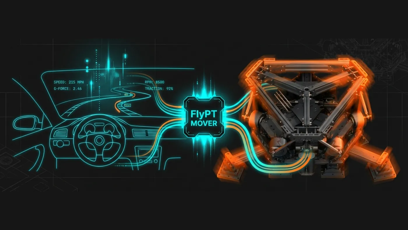
Communication architecture
Network interface. The PDK communicates over 100 Mbit Ethernet. An integrated Wi-Fi router and Ethernet switch is built into the control system, allowing both wired and wireless connection. The platform's network address is fixed and configurable during setup.
UDP: primary motion-data path. Motion commands are received as binary UDP packets on the MCP at port 38400. This is the path used by FlyPT Mover and any custom motion-cueing application.
WebSocket: tuning and telemetry path. A WebSocket bridge running on the router exposes the full tuning registry to the browser-based tuning interface. Live parameter read/write and telemetry streaming, with multi-client support: a motion-control application using UDP and a tuning application using WebSocket can run concurrently.
Tuning protocol (WebSocket, JSON)
The Tuning Interface exposes every tunable parameter as a named register. Parameters can be read and written in real time over the network without stopping the motion loop. Adjust a gain, feel the difference immediately, adjust again. The browser tuning interface uses this protocol; integrators building custom tuning tools use the same path. There is no privileged channel.
// Tuning write (browser/app → router → MCP)
{
  "type": "mc-write-all",
  "vars": { "<variable_name>": <value>, ... }
}

// Telemetry broadcast (router → WebSocket clients)
{
  "type": "mc-vars",
  "vars": { "<variable_name>": <value>, ... }
}
A browser-based dashboard running on the embedded router provides real-time telemetry visualization, parameter editing, preset management and system status. No additional software installation required. The PDK operates without an external host computer: once configured, it boots, initialises and enters a ready state independently, all manageable from your phone or computer via the web portal. Any device on the local network can access the interface.
Operation modes
- FlyPT mode. Standard mode for motion cueing applications. The MCP receives pose data via UDP from FlyPT Mover or any compatible UDP source. Recommended for sim racing, flight simulation and VR.
- Motion plan mode. Plays back a pre-calculated motion trajectory. Used for repeatable test sequences, demos, and research applications requiring deterministic motion.
- SpaceMouse mode. Real-time 6-DOF input from a SpaceMouse controller, in absolute (position-mapped) or incremental (velocity-mapped) sub-modes. Used for direct manual platform control.
Direct actuator mode
Advanced developers can bypass the inverse-kinematics layer by sending UDP packets in Direct mode (mode byte = 2). This commands the six actuators directly with per-motor position targets, treating the platform as six independent rotary motors rather than a 6-DOF pose. Appropriate for research applications and custom motion cueing implementations.
You're on your own. Direct actuator mode bypasses the high-level kinematic layer. Developers who choose this path are responsible for computing safe actuator positions from intended platform poses, including kinematic limits, workspace boundaries and safety constraints. Support and warranty cover for systems operating outside the documented control architecture is governed by the Terms of Sale & Use.
Open architecture: The PDK is not locked to specific software. The control interface is documented and accessible. Developers building custom applications or research tools can integrate directly with the motion system.
Read the full Software Integration pageSetup guides on Kinemaniacs
Chapter 07 in one line
42 bytes of UDP. If you can open a socket, you can drive the platform.
Chapter 08
Safety Architecture
A motion platform carries a person. The engineering consequences of that are non-negotiable. Safety is not a checklist appended to the design. It is embedded at every layer, so that the design relies on no single point of failure.
Note 10 · Break itEach anticipated failure, and what catches it
Each anticipated failure mode is designed to bring the platform to rest. Notice which layer catches each one. The watchdog lives in ARK Drive firmware, independent of the HKP, so a software crash on the HKP cannot prevent it from firing. That independence is the design, not a bonus.
Hardware safety
Emergency stop. A button. Press it and power to all three ARK Drive controllers cuts immediately. The platform stops. Sometimes the most sophisticated safety system is a big red button. Manual reset is required after activation; the platform does not restart automatically.
Thermal protection. Each motor has temperature sensing on motor and FET stages, streamed continuously to the control system. If temperature crosses the configured fault threshold, that motor is stopped independently. One overheating motor does not take down the entire platform.
Power monitoring. Bus voltage and per-axis current are continuously monitored by each ARK Drive. Each has its own overcurrent protection. The capacitor bank's energy recuperation is managed to prevent overvoltage during aggressive regenerative braking.
Capacitor energy constraints. Unlike batteries of the same size, the capacitor bank holds a much smaller quantity of energy. In a sustained high-demand event, the equivalent of a vehicle rollover where the platform is continuously commanded against its limits, the capacitors deplete and the system shuts down rather than continuing to operate at undefined voltage.
Firmware safety
Watchdog timer. The HKP sends a heartbeat to each ARK Drive continuously over CAN. Each ARK Drive monitors this heartbeat independently. If heartbeats stop arriving, the ARK Drive stops its motors. The watchdog is implemented in ARK Drive firmware, independent of HKP software. A software crash on the HKP cannot prevent it from firing.
Encoder validation. Each ARK Drive continuously compares commanded motor position to the position reported by the 21-bit encoder. If the error exceeds a defined threshold, the controller flags a fault, reduces velocity and investigates. If the error persists or grows, the motor stops and a fault is logged.
Communication validation. Every CAN message between HKP and ARK Drive includes a CRC checksum. Any message failing validation is discarded: not acted upon, not treated as a valid command. A message queue timeout triggers the same watchdog response as a missed heartbeat.
Software safety
Workspace boundary enforcement. The HKP maintains a real-time model of the platform's position relative to its physical limits. Software boundaries sit inside the mechanical limits, providing a buffer zone the platform never reaches under normal operation. On approach, the control system begins deceleration predictively, calculating stopping distance and initiating the sequence with enough margin to stop before the limit.
Boundaries are configurable per application. A research application requiring precise slow motion near the envelope edges can configure different margins than a racing simulator operating primarily in the central region at high speed.
Configurable current limits. Each motor has a hard ceiling on continuous current, regardless of what the control system requests. User-configurable, set per motor.
Motion profile constraints. Maximum acceleration and maximum jerk limits are enforced at all times, designed to keep motion within the structural limits of the platform and the profile limits set in firmware.
Outside the three layers: presence awareness
Two mmWave presence radars are fitted as standard, and the platform supports up to six for full 360° coverage of the operating clearance zone. They give supplementary awareness of people or objects near the platform; they are not one of the three safety layers: the platform's safety guarantee comes from the hardware-limited envelope and power design above, not from sensor-based detection, and nothing in the safety architecture depends on how many radars are fitted.
Failure modes and outcomes
| E-stop pressed | Immediate power cut to all motors. Manual reset required. |
|---|---|
| HKP software crash | ARK Drive watchdog fires. Motors stop. |
| CAN bus failure | Watchdog fires. Motors stop. |
| Encoder failure | ARK Drive flags fault. Motor stops independently. |
| Motor overtemperature | Independent motor shutdown on fault threshold. Other axes continue. |
| Workspace limit approached | Predictive deceleration. Stop before limit. |
| Pneumatic pressure loss | Platform descends slowly to mechanical stops. No sudden drop. |
| Architecture | Three-layer: hardware E-stop, firmware watchdog, software boundaries |
|---|---|
| Emergency stop | Power-cut to all ARK Drives |
| Thermal protection | Per-motor thermal sensing |
| Firmware watchdog | Heartbeat-based per ARK Drive; motors stop if heartbeats stop arriving |
| Communication integrity | CRC-validated CAN bus (2 Mbps) |
| Workspace boundaries | Configurable per-axis limits + per-motor current limits |
Designed to stop, not to run away.
Each of these failure modes, whether power loss, communication drop or firmware fault, is designed to bring the platform to rest, holding position or settling to its stops, rather than into uncontrolled motion.
Chapter 08 in one line
Three layers, each designed to end in a stopped platform.
Chapter 09
The Motion Envelope
What the platform can do, and why the perceptual experience of motion extends well beyond what the physical numbers suggest.
Note 11 · Six axesThe platform, axis by axis
The production PDK geometry, solved live: the same mesh and closed-form inverse kinematics as the store bench, with every rotor, connecting rod and air cylinder re-posed on each change, the same solve the HKP runs at 3.3 kHz internally. The bars are the crank angle each ARK Drive is commanded, what the motors actually receive. Move one axis and watch all six legs respond: that is the parallel mechanism from Chapter 1, working. Each slider stops at that axis's nominal limit; push several at once and the legs ask for more travel than any one axis allows, which is exactly what the workspace enforcement in Chapter 8 catches before the platform reaches it.
The six axes
Three translate the platform through space, three rotate its orientation, and all six operate simultaneously. Surge: forward and backward, the sensation of braking and acceleration. Sway: left and right, lateral G pushing you into the seat through a corner. Heave: up and down, a kerb strike, a bump over a crest. Roll: banking left or right. Pitch: nose up, nose down; braking dive and acceleration squat. Yaw: turning around the platform's vertical centre.
The nominal envelope
The nominal envelope is the range achievable operating a single axis at a time, all others at neutral. The axes trade against each other, so no axis reaches its nominal limit while the others are working. A combined-axis, or extended, envelope is a real and larger thing, but it is not published here: see the note under the table.
Note 12 · EnvelopeNominal, axis by axis
Heave is the axis most directly limited by actuator stroke — 117.35 mm, and it is the one axis with no geometric trade left to make. Surge is the widest at 158.23 mm, and the only axis whose limits are asymmetric about neutral.
| Surge | −75.49 mm to +82.74 mm · 158.23 mm total |
|---|---|
| Sway | −71.92 mm to +71.92 mm · 143.85 mm total |
| Heave | −58.68 mm to +58.68 mm · 117.35 mm total |
| Pitch | −7.98° to +8.09° · 16.07° total |
| Roll | −8.68° to +8.68° · 17.36° total |
| Yaw | −9.80° to +9.80° · 19.60° total |
All six are read from the T1 firmware boot banner, 2026-07-07 capture. The firmware carries no envelope literals: it computes its limits at boot from the platform geometry, and refuses an out-of-envelope pose rather than clamping it. The envelope table on /technology/ carries the same six figures with their source.
Why the physical range feels larger than the numbers
A platform with ±60mm of heave and ±8° of pitch is a physically compact machine. The numbers are not large in absolute terms. But the perceptual experience of motion in a well-configured platform extends far beyond what those numbers suggest. The reason is motion cueing.
The human vestibular system detects acceleration, the rate of change of velocity, not sustained velocity or sustained tilt. A constant 2G lateral force in a racing car continues indefinitely. A platform with ±72mm of sway cannot. Motion cueing works with that: a correctly executed onset cue followed by a controlled washout reproduces the most perceptually important components of sustained acceleration within a bounded envelope. A convincing approximation, not the complete physical loading of the real vehicle.
Onset cue. When an acceleration event occurs, hard braking, a kerb strike, a landing, the platform moves rapidly in the corresponding direction. The vestibular system detects the acceleration onset. The perceptual event is registered as real.
Washout. The platform slowly returns toward neutral, at a rate below the threshold of vestibular detection. The user does not feel the return. The platform is now positioned to deliver the next onset cue.
Note 13 · The trickOnset and washout
The dot is the platform. The lower trace is what the vestibular system registers. The onset is fast and sharp: the brain logs a real acceleration event. The return is slow, deliberately below the detection threshold, so the platform quietly resets to centre without the rider noticing it moved back. The platform is now ready to deliver the next onset cue. Sustained force is an illusion assembled out of onsets.
The PDK's 1 kHz internal control loop and sub-millisecond command-to-actuator latency are directly relevant here. Motion cueing algorithms require high-frequency updates to track telemetry accurately and produce onset cues with the timing precision the vestibular system requires. A platform with higher latency produces onset cues that are perceptibly late. The motion arrives after the brain has already processed the absence of it. The PDK's response speed is what makes motion cueing feel convincing rather than approximate.
Acceleration capability
Peak acceleration is 3 g, software-limited in firmware, a brief onset rather than a sustained load. The direct-drive architecture is what makes this possible: with no gearbox absorbing energy or introducing mechanical delay, and with pneumatic weight compensation removing the static gravity burden, the full 30kW burst capability of the capacitor bank is available for instantaneous acceleration.
What the envelope supports
Sim racing
The full pitch range covers braking dive and acceleration squat. Heave captures kerb strikes and road surface texture. Sway delivers lateral G onset through corners. Combined with high-frequency road texture reproduction, the perceptual experience covers the full range of what a racing driver feels.
Flight simulation
Pitch and roll cover coordinated turn entries, climb and descent attitude. Heave reproduces turbulence, flare and runway contact. Yaw covers directional inputs and crosswind effects. The combined envelope is sufficient for general aviation, aerobatic onset cueing and rotary-wing hover dynamics.
Research and vestibular studies
The precisely characterised envelope, combined with 21-bit encoder resolution and 1 kHz internal control, gives researchers a platform with known, repeatable motion delivery. Direct drive removes gearbox backlash as a major source of tracking error between commanded and delivered motion; what remains is a property of the complete mechanical and control system, characterised at the platform. Crucially for studies correlating motion onset with EEG, fMRI, HRV or eye-tracking events, the bare-metal control architecture delivers deterministic timing at the millisecond timestep.
XR and VR
Sub-millisecond command-to-actuator latency places the PDK's motion delivery well inside the sensorimotor binding window, the interval inside which the brain accepts visual and vestibular signals as belonging to the same event.
| Footprint | 1.00 × 1.00 m, PDK platform (1.20 × 1.00 m with the PDK Racer chassis) |
|---|---|
| Height | 0.50 m retracted; extends during operation |
| Payload | 250kg maximum |
The envelope is compact. What happens inside it is not.
The PDK does not ask the nervous system to accept a reduced experience because the physical range is bounded. It asks the vestibular system a different question: given onset cues that arrive within a millisecond of the command, at 21-bit resolution, can you tell the difference? For the vast majority of motion events that occur in any simulation, the answer is no.
Chapter 09 in one line
The envelope is compact. What happens inside it is not.
Chapter 10
Complete Specifications
All PDK performance parameters, physical dimensions and system requirements in one place.
Note 14 · Spec indexEvery spec row in this document
Every spec row on this page, indexed. The chapter tag on each line jumps to where that number is explained.
Motion performance
| Degrees of freedom | 6-DOF (surge, sway, heave, roll, pitch, yaw) |
|---|---|
| Platform type | Stewart-Gough parallel manipulator |
| Surge travel | 158.23 mm |
| Sway travel | 143.85 mm |
| Heave travel | 117.3 mm |
| Yaw range | 19.60° total (±9.80°) |
| Pitch range | 16.0° total (±8.0°) |
| Roll range | 17.3° total (±8.7°) |
| Peak acceleration | 3G (safety-limited in production) |
| Command-to-actuator latency | <1 ms (command to actuator) |
Control system
| Control rate | 1kHz (1,000 Hz), internal |
|---|---|
| Inverse kinematics | 3.3 kHz, internal |
| Drive loop | 8 kHz per motor (125 µs), internal |
| Processors | 2× ARM Cortex-M7 microcontrollers (600MHz) |
| Motor controllers | 3× ARK Drive (2 motors each, custom firmware) |
| CAN bus speed | 2 Mbps |
| Encoder resolution | 21-bit (221 = 2,097,152 positions/rev, 0.000171661° per count) |
Power system
| AC mains input | 100–290VAC (universal, runs on any global grid) |
|---|---|
| Bus voltage | 53.3V |
| Continuous current | 56A |
| PSU continuous power | 3kW |
| Capacitor bank | 1.41 F (3 × 0.47 F, 63 V) |
| Peak burst power | 30kW |
| Active draw (user on, motors armed) | ≈30W AC |
| Static hold (platform up, pneumatics carrying the weight) | ≈15W AC |
| Outlet requirement | Standard domestic |
Physical
| Payload | 250kg maximum |
|---|---|
| Footprint | 1.00 × 1.00 m, PDK platform |
| Weight compensation | 3 pneumatic cylinders, 50 mm bore × 140 mm stroke, 6.0 bar max |
| Patent | CA 3217174 C |
| Inventors | Louis Hajichristou & Michael Gregoriades |
| Origin | Nicosia, Cyprus |
Software
| Primary integration | FlyPT Mover (UDP to MCP, port 38400) |
|---|---|
| Parameter interface | Tuning Interface, real-time over network |
| Tuning UI | Browser-based dashboard (local network) |
Safety
| Architecture | Three-layer (hardware E-stop, firmware watchdog, software boundaries) — see Chapter 8 |
|---|---|
| Emergency stop | Power-cut to all ARK Drives |
| Thermal protection | Per-motor thermal sensing |
| Firmware watchdog | Heartbeat-based per ARK Drive; motors stop if heartbeats stop arriving |
| Communication integrity | CRC-validated CAN bus (2 Mbps) |
| Workspace boundaries | Configurable per-axis limits + per-motor current limits |
Chapter 10 in one line
Every number in the document, in one place.
Ten chapters. One question.
What kind of engineering gives the human nervous system nothing to distrust?
Every decision in this document is an answer to that question. The architecture that distributes load across six legs simultaneously. The motors with no transmission between command and movement. The patent that removes the static load so the motors only ever deliver motion. The encoder that resolves positions below the detection floor of the vestibular system. The control system that closes its loop inside the time the nervous system would need to detect lag.
That is the engineering. The result is not performance in the conventional sense. It is neurological trust. The human in the seat receives a signal the nervous system accepts as real.
Configure one The latency problem Compared, spec for spec Continue in the Journal
Questions
Technical FAQ
The architecture, physics and engineering questions that come up most often.
What does "sub-millisecond command-to-actuator latency" actually mean in practice?
It means the time from when a motion command enters the platform's control system to when the actuators begin responding is under 1 millisecond. It describes the PDK control loop; total perceived latency in a sim rig also depends on the PC, game engine and motion software in the chain.
How does the pneumatic weight compensation work, and why is it patented?
The patent (CA 3217174 C) covers a dynamically programmable air spring that counterbalances the static weight of the platform and rider. At any given moment of motion, the locked air-spring carries the load mechanically; brief equilibration pulses re-trim pressure only when payload changes. By counteracting gravity mechanically, the motors are freed from fighting the platform's own weight, allowing them to direct their full capability toward dynamic motion. The result is more acceleration, more responsiveness, and less heat, from motors that would otherwise spend most of their capacity just holding the platform up.
Why 21-bit encoders? What's wrong with the 14-bit encoders most platforms use?
A 14-bit encoder has 16,384 positions per revolution. A 21-bit MT6835 has 2,097,152, 128× more. High-frequency surface detail (kerb rumble, road texture, granular slip) is encoded in very small, very fast actuator movements. If your position feedback can't resolve movements with enough resolution, those sensations are invisible to the control system and never reach the platform. The PDK can. Road texture, tyre grain, engine harmonics. These aren't simulated with large movements, they're reproduced with microscopic ones.
How does motion cueing work, isn't the platform too small to reproduce real g-forces?
Correct. No simulator platform, including $500,000 professional full-flight simulators, can reproduce sustained g-forces directly. Motion cueing is the science of using onset cues and tilt coordination to create physiologically plausible sensations within the platform's physical limits. For a sustained acceleration force, the platform initially translates (giving you the onset cue), then gradually tilts to use gravity as a substitute for sustained force, slowly enough that the vestibular system doesn't perceive the rotation, only the sustained tilt component. Washout algorithms return the platform to neutral between cues. The PDK's sub-millisecond command-to-actuator latency and 21-bit resolution make onset cues particularly sharp. The initial transient is where human perception is most sensitive, and the PDK reproduces it accurately.
What are the power and space requirements?
Power: designed for standard domestic power (100–290VAC, 50/60Hz). Typical operating draw is ~30W; peak motion bursts are handled by the capacitor bank, not drawn continuously from the outlet. Circuit availability varies by region — verify local supply before install. Footprint: 1.00 × 1.00 m for the PDK platform, 1.20 × 1.00 m with the PDK Racer chassis.
Does it work for flight simulation, not just racing?
Yes. The PDK is a full 6-DOF platform with all six axes simultaneously available, which is essential for flight simulation (aircraft motion couples all axes simultaneously in ways that ground vehicles don't). The pneumatic weight compensation is particularly relevant for flight use. Extended sessions place less thermal load on the motors than a design that carries the static weight on the motors, because the motors are doing significantly less work during slow, sustained flight manoeuvres.
What safety systems prevent the platform from moving dangerously?
The PDK has a three-layer safety architecture. Hardware layer: an emergency stop that cuts power to all ARK Drives, per-motor thermal sensing, and mmWave presence radars for supplementary awareness of the operating clearance zone — two as standard, up to six for 360° coverage (not one of the three safety layers). Firmware layer: a heartbeat-based watchdog on each ARK Drive (if heartbeats stop arriving, motors stop), continuous encoder validation, and CRC-validated communications. Software layer: configurable workspace boundary enforcement and per-motor current limits. Chapter 8 covers the full architecture.
How does a motion simulator work?
Simulation software turns game or vehicle telemetry into a target pose for the platform, six numbers: surge, sway, heave, roll, pitch, yaw. The PDK receives that pose over UDP, solves the inverse kinematics in closed form to get six actuator positions, and sends them to the motor controllers at 1kHz, an internal rate. Direct-drive motors move the platform with no gearbox in the path; a dynamically programmable air spring carries the static weight so the motors only deliver motion; 21-bit encoders close the loop. Motion cueing (onset cues plus slow washout) makes a compact envelope feel far larger than its millimetres. Chapter 1, Chapter 5 and Chapter 9 cover each step.
How long does it take to set up and start using?
Self-assembly is supported with full documentation provided. Unpack, position, connect power and Ethernet. Software setup (FlyPT Mover + game profile) takes roughly 30–60 minutes for a first-time installation, or as little as 10 minutes if you're working from a community-shared profile for your specific title. The guides on Kinemaniacs cover per-game setup.