It cannot see past a gearbox
The loop closes on the motor shaft. Anything a transmission does after that point — a gap at reversal, a belt taking up slack — is outside the loop and invisible to it.
Engineering · Control
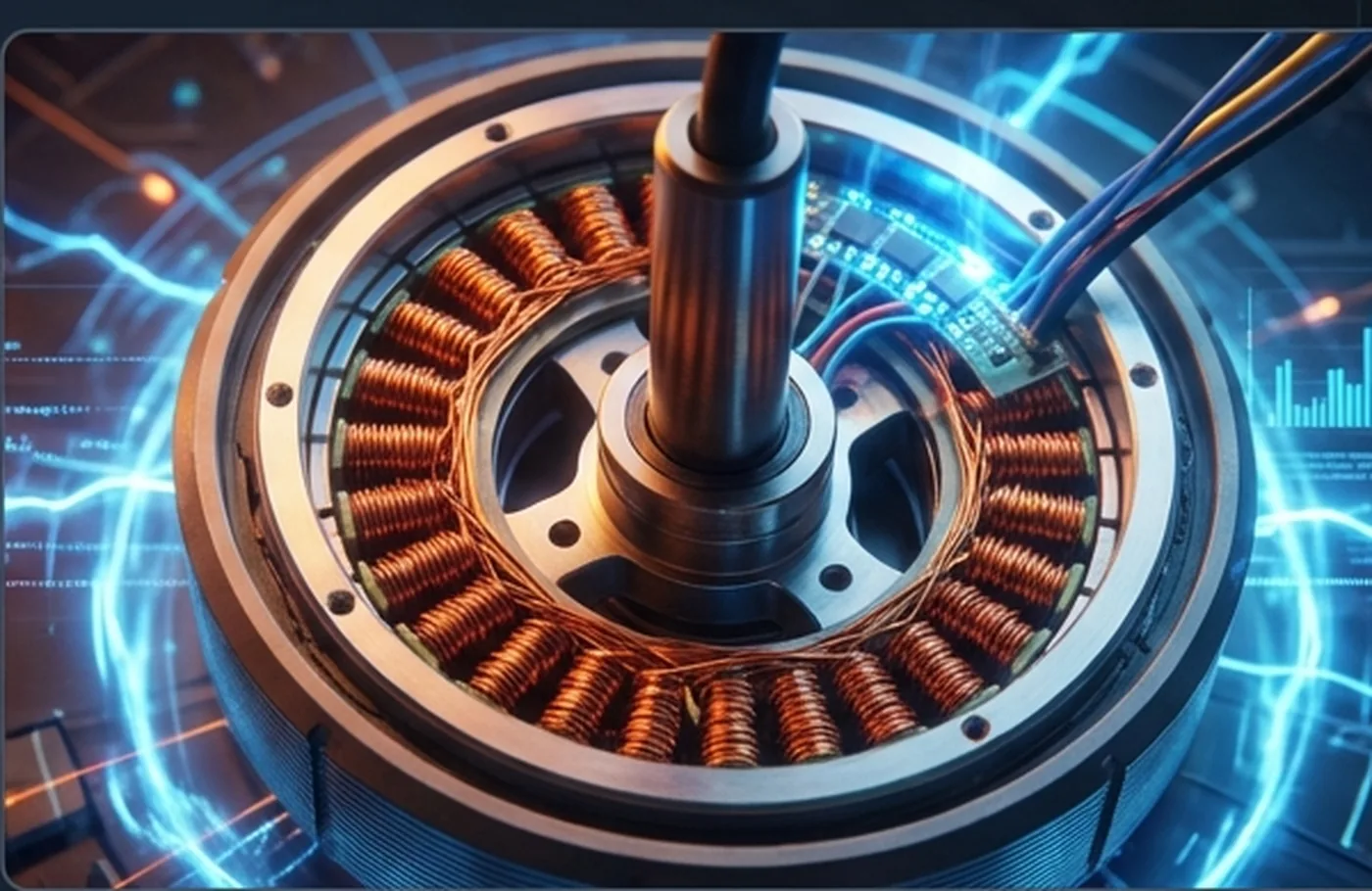
A brushless motor is three coils and a set of magnets. Energise the coils crudely and you get torque that rises and falls as the rotor turns — you feel it as roughness. Field-oriented control energises them with the rotor angle in hand, so the field stays square to the magnets and the torque comes out flat.
The idea
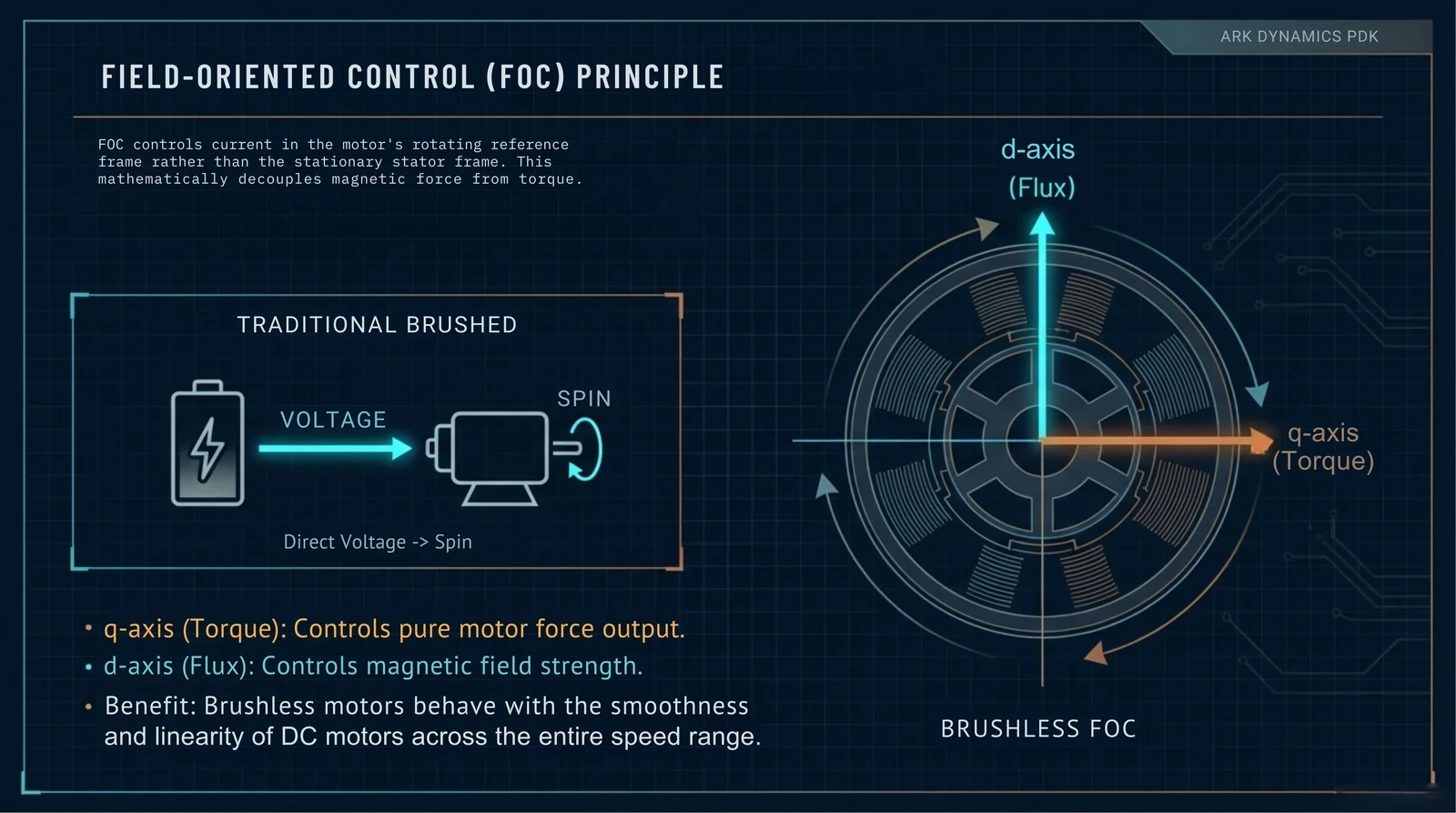
Torque in a permanent-magnet motor is greatest when the stator field is perpendicular to the rotor field, and falls away as that angle changes. Field-oriented control measures where the rotor is, then computes the three phase currents that put the field exactly where it produces torque and nowhere else. Do it fast enough and the rotor never gets ahead of the calculation.
Why the rate matters
The loop has to close faster than the rotor can move meaningfully. At 8 kHz there are 8,000 corrections per second per motor, each one starting from a fresh absolute encoder reading rather than an estimate.
| Step | Per cycle | Detail |
|---|---|---|
| Cycle period | 125 µs | 8 kHz, set by the drive's own hardware timer |
| Encoder read | 1 | 21-bit absolute position over SPI, not an extrapolation |
| Current loop | 1 | Phase currents resolved into torque-producing and field-producing parts |
| Position loop | 1 | Closed in the same cycle, so position and current never disagree about the angle |
| Motors doing this | 6 | Independently, each with its own drive |
The 8 kHz figure describes the drive loop inside the machine. It is not a telemetry rate, a refresh rate, or anything your PC will observe.
The boundary
Field-oriented control makes the torque smooth. It does not make the machine stiff, and it cannot recover information the mechanism has already thrown away.
The loop closes on the motor shaft. Anything a transmission does after that point — a gap at reversal, a belt taking up slack — is outside the loop and invisible to it.
Control is only as good as the angle it is given. A coarse or badly mounted encoder produces confident, smooth, wrong torque.
Holding a static load with current is a thermal problem, and it is the reason the platform's weight does not rest on the motors in the first place.
Where the current comes from
Field-oriented control spends current, and a six-motor platform's demand is spiky — hard at the onset of a movement, near nothing between them. Sizing a supply for the peak would mean a large, expensive unit idling most of the time, so the platform does not.
| Element | Figure | Note |
|---|---|---|
| Supply input | 100–290 VAC | Universal — any domestic grid, single phase, no three-phase installation |
| Supply output | 53.3 V | The DC bus the drives run from |
| Supply continuous | 56 A | 2,985 W — the figure published elsewhere as “3 kW” |
| Capacitor bank | 1.41 F | Three 0.47 F units. Stores energy between movements and releases it at the peak |
| Peak demand | 30 kW | Instantaneous, from the bank rather than from the wall |
The bank is also why regenerative braking is not wasted: energy coming back out of a decelerating motor is absorbed and released within the same motion cycle. What we still do not have is a manufacturer part number for the supply itself — the electrical specification above is consistent and traceable, the part is not named anywhere in our material.
Keep reading
Why the loop closes on something that is bolted to the load rather than geared to it.
Where this 8 kHz loop sits in the full path from your input to the platform moving.
What you receive, what it costs, and what you assemble.